Description
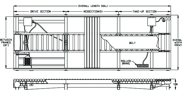
Drive Sections
Freestanding “weldments” available in lengths of 3’ and 6’-6”. Additional cross bracing is provided to minimize flexing of unit.
- 7” dia. Drive Pulley with vulcanized rubber surface; 1-1⁄2” dia. shaft mounted in precision pillow block bearings.
- Drive has a totally enclosed industrial rated 1750 R.P.M. motor mounted to an in-line reducer for the speed reduction as specified. Drive motor and in-line reducer are grease filled and maintenance free for a two-year period.
- Drive package located within and under the side frames and requires no pits or floor work.
- Speeds of 45 and 60 FPM
- Motors of 1 and 1-1/2 HP
- System Voltage is 460575 volt, 3 phase, 60 hertz with 115 volt, single-phase control voltage.
Take-Up Sections
- Freestanding “weldments” available in lengths of 3’ and 6’-6”. Additional cross bracing is provided to minimize flexing of unit.
- Take-Up Pulley is 4” dia. crowned with 18” face width; 1-1⁄4” dia. shaft mounted in precision pillow block bearings with captive screw set horizontal adjustment
for belt tracking.
Midsections
Modular design with two air mounts per section.
- Lengths from 1’ through 8’-0” in 3” increments.
- (Zoned conveyor requires midsections to match zone length and “double” air mounts.)
Features
End Guards
Safety Guards are provided at the ends of Drive or Take-Up Sections, which are exposed to cover moving drive components.
Drive Motor Disconnects
Three-phase switches provided for all drive motors, which conform to the maintenance “lock- out/tag-out” requirements.
Internal Photoeyes
All photoeyes are mounted underneath the conveyor to eliminate tripping hazards and protect them from damage.
Normally Off Controls
Drive Motor is energized only when material is present on the conveyor which reduces unwanted wear on the conveyor and provides energy conservation for the end user.
Crosswalks
Employee crossover is provided with “drop-in” crosswalks. These units simply replace a roller and can be easily added or moved when required.
Zero Energy Compliance
Electrical and Pneumatic Disconnects at the Control Panel allow system to be totally disabled includ- ing the exhaust of trapped air in the system. OSHA Regulation #29CFR1910.147.
Installation Materials (optional)
Engineered Conduit Layouts and prelabelled Wire Bundles allow installation down time to be mini- mized.
Chain-Assist Rollers (optional)
Chain-Driven Rollers are provided at the ends of drives and/or take-up sections when drive is re- quired to the end rollers.
Roller Surfacing (optional)
Load Carrying Rollers can be “knurled” to provide additional drive in pallet applications.
Specifications
Sideframes
5” x 6.7# Structural Channel with 1⁄4” x 21⁄2” “drop-in” roller support bar. • Structural load rating is 1,000 lbs. per foot.
Load Carrying Rollers
2-1⁄2” O.D. x 10 Ga. wall “Drop-In” Style
-
- Counter-bored to accept a grease-packed Teflon sealed bearing (lubricant is waterproof and high temperature) having twelve hardened ball bearings.
- Rollers supported by a “captivated” 11/16” hex shaft.
- Load rating is 750 lbs. per roller.
Pressure Tray & Pressure Tray Rollers
2” x 2” x 1⁄4” Structural Angle Weldment with 6” dia. Air Mounts.
• Racks are vertically adjustable for increased or decreased drive against Load
Carrying Rollers.
• Universal pressure rollers frame permit easy field conversion from standard power
to accumulating conveyor.
2-1⁄2” O.D. x 10 Ga. wall “Spring Retained”
• Counter-bored to accept a grease-packed bearing supported by a 5/8” hex shaft. • Pressure rollers are located alternately between Load Carrying rollers (approx 6”). • Return Rollers are supported at each support leg.
Belting
15” wide Nylock cord woven with PVC face providing 120 lbs. per inch of width tensile strength. • Belts are available (upon request) cut to length and prelaced with clippard lacing.
Roller Brakes
Floor Mounted Assemblies with adjustable upper limits to provide positive contact with the load-car- rying roller to prevent coast.
- Available in lengths of 10” and 34” and include 6” diameter Air Mount.